A laboratory centrifuge is a lab device, working under a motor, which spins liquid samples at high speed. It does a centripetal acceleration that separates substances of greater and lesser density when suspended particles settle down the fluid in which they are dispersed. This is due to their response to the centrifugal acceleration.
Though glass centrifuges can be exploited for various solvents and cleansed thoroughly by autoclaving they are quite costly. Whereas, plastics are less expensive and easily disposable than cleansed.
Types:
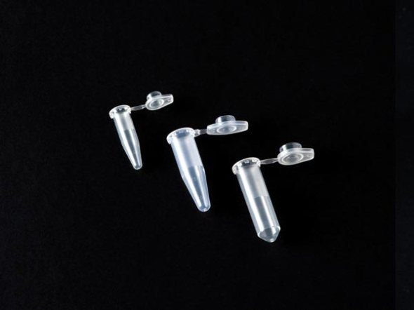
Microcentrifuges – for micro tubes
Clinical centrifuges – used like blood collection tubes, low-speed devices
Multipurpose bench top centrifuges – devices for a broad range of tube sizes
Stand alone centrifuges- ultracentrifuge
Centrifuges may also have refrigerators.
Working:
The tubes loaded in a laboratory centrifuge will need to balance the loads by either exploiting samples or balance tubes which weigh equally or by various balancing patterns. While the rotor inside motions, centrifuge or the operator due to the heavy force generated.
Basic necessities:
Automatic rotor imbalance detection that disables the spin when an inequality of balance is sensed may be necessary.
Locking the centrifuge lid:
Checking, monitoring and maintaining for any worn out rotor or other parts in the centrifuge.
Shielding the centrifuge, the main reason being displacement of the centrifuge itself, chronically affecting the staff.
Procedural and cautious handling of staff.
Preventing dispersion of ultramicroscopic solid or liquid particles into laboratory air from risky samples during centrifugation by implementing aerosol-tight gaskets.
Steps:
Load the rotor with the samples within a hood
Fix the rotor lid on the rotor.
Move the aerosol-tight system of rotor and lid to the centrifuge.
Fix the rotor within the centrifuge without opening the lid.
After the centrifugation, remove the materials with the lid before opening it.
A Nomogram graph usually contains three parallel scales graduated for different variables so that when a straight line connects values of any two, the related value may be read directly from the third at the point intersected by the line.
We can use nomograms for converting Relative Centrifugal Force – RCF to Rotations per Minute – rpm for a rotor of a given radius. A ruler or other straight edge lined up with the radius on one scale, and the desired RCF on another scale, will point at the correct rpm on the third scale.
Relative Centrifugal Force = 0.00001118 × rotational radius (cm) × (rotating speed /minute) ^2
These days, centrifuges have a button for automatic conversion from RCF to rpm and vice versa.
Ref: Google Books/ Articles/ Free encyclopedia / Wikipedia
